Fabry-Perot data cubes.
Introduction: what is "data cubes"?
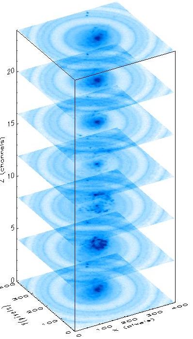
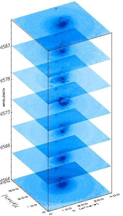
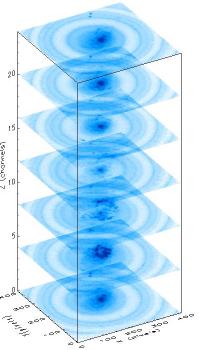
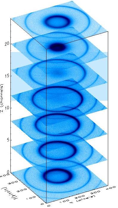
 Observations with the IFP consist of successive acquisition of a few dozen images of interference rings from the object (or from a calibration lamp) when changing the optical path between the flat-parallel plates. The radius of the rings is a function of wavelength and gap between the plates of the interferometer. Radial distance of the rings is function of wavelength and etalon gap. Different rings on individual image correspond to different interference orders. The complete set of such images which fills the free spectral range of the interferometer is called
a scanning cycle. After a special reduction, these images may be represented as a "data cube". X and Y dimensions of this cube are equivalent of coordinate axes on CCD-frame ("spatial coordinate"). Z-axis is a "spectral coordinate". We used 32-36 scanning steps and our
data cube has maximal size 2048x2048x34 elements. Usually setting small cubes 512x512x32elements if CCD reading in 4x4 binning mode. Observations with the IFP consist of successive acquisition of a few dozen images of interference rings from the object (or from a calibration lamp) when changing the optical path between the flat-parallel plates. The radius of the rings is a function of wavelength and gap between the plates of the interferometer. Radial distance of the rings is function of wavelength and etalon gap. Different rings on individual image correspond to different interference orders. The complete set of such images which fills the free spectral range of the interferometer is called
a scanning cycle. After a special reduction, these images may be represented as a "data cube". X and Y dimensions of this cube are equivalent of coordinate axes on CCD-frame ("spatial coordinate"). Z-axis is a "spectral coordinate". We used 32-36 scanning steps and our
data cube has maximal size 2048x2048x34 elements. Usually setting small cubes 512x512x32elements if CCD reading in 4x4 binning mode.
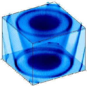
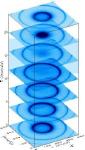
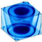
This figure shows example of ordinary data cube. Its interference rings of Ne line which use for phase calibration (convert object
data to wavelength-scale).
|
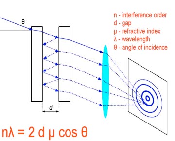 The condition of maximum of the interference pattern.
| 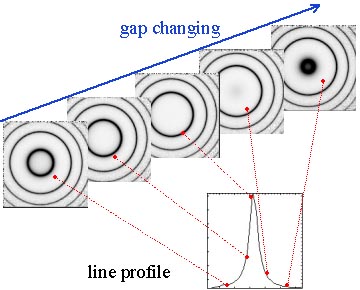 The scheme of the scanning sequence.
|
Calibration cubes
Calibration set with Fabry-Perot including standard frames for
CCD observation such as BIAS and DARK frames. Moreover will be
obtained NEON-line calibration cube and FLAT-FIELD calibration
cube for each setting of narrow-band order-separate filter.
NEON cube
| Line wavelength is a function of radial distance in each channel
of the original OBJECT data cube. Therefore individual spectra in each pixel has a shift along wavelength-axis. Set images of ring picture from the reference emission line of He-Ne-Ar lamp need use for wavelength calibration. NEON data cube is construction from that images. Then a map of phase shifting formed from data cube. |
FLAT-FIELD cube 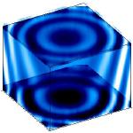
|
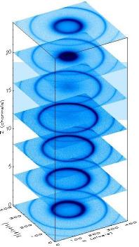
For flat fielding calibration uses the whitelight lamp
with cogtinuous spectra. Flat Field calibration need for two reasons:
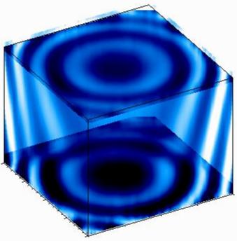
Correction by a spectral modulation which narrow-band filter leads in the observed data cube. FWHMs of filters are about 8-20 A and least or equal than interfringe of the IFPs.Terefore spectral modulation can see in FLAT-FIELD cube as "broad rings" in each image (look this figure for example).
Correction by pixel-to-pixel sensitivity variation on CCD-detector,
in homogeneusities in the filter structure, optical surfaces. Such flat field is a usually FLAT as in CCD-photometry.
|
Wavelength calibration
Phase surface
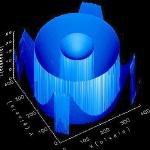
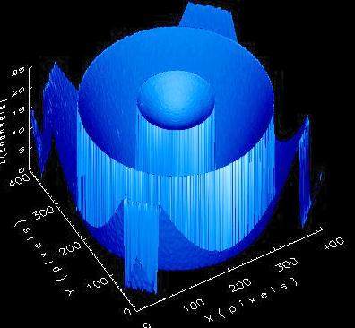
| Phase map is a 2D-image where value of each pixel is corresponding to a relatively shift the calibration emission line's center in NEON data cube. Shape of the emission line is a Airy profile really, but it is approximated as Lorentzian very well. It has a Lorentzian profile in radial direction, and has breaks in regions where interference order takes turn.
|
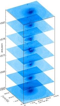
ORIGINAL OBJECTs CUBE
| ORIGINAL NEONs CUBE
| WAVELENTGH's CUBE
|
|
System of rings in the OBJECT original cube is night sky lines. Phase surface
are extracted from NEON data cube and uses for wavelength calibration procedure
(linearization). Individual spectra in the OBJECT cube are shifted by value of
phase shifting and re-scaled to wavelength units. Each channel in the output OBJECT cube like as a image in narrow filters which has FWHM < 1 A.
|
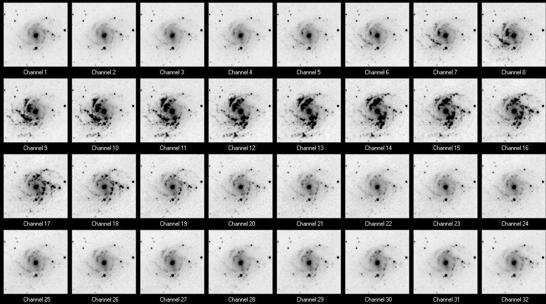
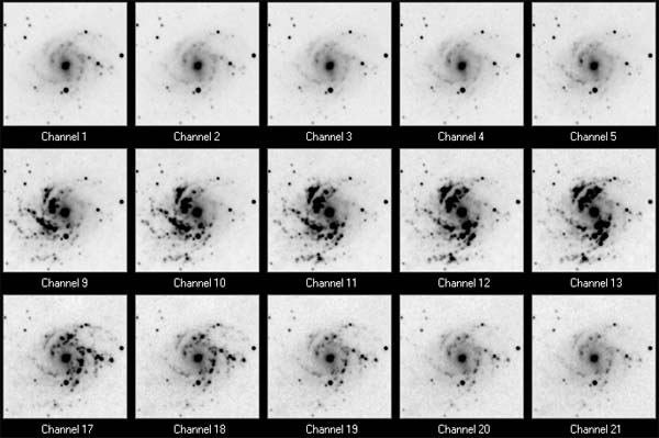
The example of wavelength corrected data
|
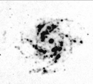
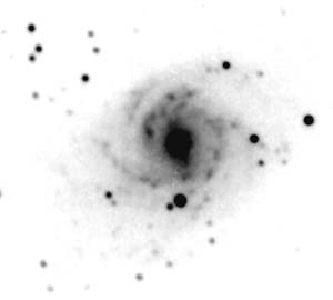
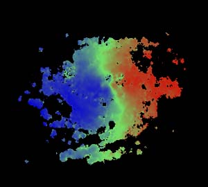
Here the the data for spiral galaxy NGC 2339 which was observed in November, 2002
at the 6m telescope with SCORPIO-IFP in H-alpha emission line. |
The channel map (fragment). Click on the image to see all channels.
 |
Ha image
| Continuum
|
Velocity field
| Ha profiles in the nucleus 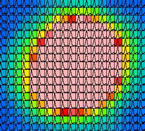
|
Click here for more examples.
 Observations with the IFP consist of successive acquisition of a few dozen images of interference rings from the object (or from a calibration lamp) when changing the optical path between the flat-parallel plates. The radius of the rings is a function of wavelength and gap between the plates of the interferometer. Radial distance of the rings is function of wavelength and etalon gap. Different rings on individual image correspond to different interference orders. The complete set of such images which fills the free spectral range of the interferometer is called
a scanning cycle. After a special reduction, these images may be represented as a "data cube". X and Y dimensions of this cube are equivalent of coordinate axes on CCD-frame ("spatial coordinate"). Z-axis is a "spectral coordinate". We used 32-36 scanning steps and our
data cube has maximal size 2048x2048x34 elements. Usually setting small cubes 512x512x32elements if CCD reading in 4x4 binning mode.
Observations with the IFP consist of successive acquisition of a few dozen images of interference rings from the object (or from a calibration lamp) when changing the optical path between the flat-parallel plates. The radius of the rings is a function of wavelength and gap between the plates of the interferometer. Radial distance of the rings is function of wavelength and etalon gap. Different rings on individual image correspond to different interference orders. The complete set of such images which fills the free spectral range of the interferometer is called
a scanning cycle. After a special reduction, these images may be represented as a "data cube". X and Y dimensions of this cube are equivalent of coordinate axes on CCD-frame ("spatial coordinate"). Z-axis is a "spectral coordinate". We used 32-36 scanning steps and our
data cube has maximal size 2048x2048x34 elements. Usually setting small cubes 512x512x32elements if CCD reading in 4x4 binning mode.