|
|
|
The beam pattern
and the polarization characteristics
of the radio telescope RATAN-600
E.K. Majorova, SAO RAS
Results ara presented of calculation of the Mueller matrix elements
 of the radio telescope RATAN-600 that connect the the Stokes parameters
at the input and output of the antenna setup of the radio telescope.
The computation is performed with allowing for the diffraction effects in the
space between the primary and secontary mirrors and for limited width of the
primary mirrow ring. The proportion of spurious linear and circular
polarization from the antenna is estimated when modeling passage of extended
across the beem pattern.
|

|

|
|
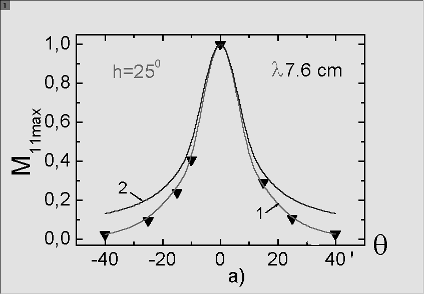
òÉÓ.2.
Maxsimum of values of the BP in different
horizontal sections for the wavelength  7.6
cm - (a) and for the wavelength 7.6
cm - (a) and for the wavelength
 3.9 cm -
(b). Curves 1 is computed in the Frenel diffraction approximation,
Curves 2 - in approximation of geometrical optics, the triangles are the
experimental values derived from observations of hte point source
1830-211 (h=25o). 3.9 cm -
(b). Curves 1 is computed in the Frenel diffraction approximation,
Curves 2 - in approximation of geometrical optics, the triangles are the
experimental values derived from observations of hte point source
1830-211 (h=25o).
|
|
The calculations carried out with provision for the diffraction effects and also
more correct allowance for thr vertical size of the reflected elements of the
primary mirror made possible revision of the shape of the BP of the radio telescope
RATAN-600 both in intensity and polarization. The power beem patterns of the
radio telescope and the Mueller matrix elements computed with allowance made for
these effects have a smaller extent in the vertical plane than those calculated in
approximation of geometrical optics. The reduction of the solid angle of the BP
proved to be the more considerable the lower elevation of the source and the
longer of the wavelength. From this it follows that at long wavelengths the effect
of confusion will be far weaker than it was assumed earlier.
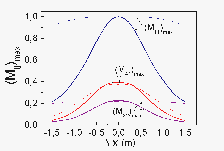
Allowance for the diffraction effects causes narrowing of the aberration-free zone
of the radio telescope near zenith and disturbance of antisymmetry of the element
 with respect to the central horizontal
section ( the maximum (minimum) values of the element in the upper half-plane
differ from the minimum (maximum) values of the lower half-plane in magnitude). with respect to the central horizontal
section ( the maximum (minimum) values of the element in the upper half-plane
differ from the minimum (maximum) values of the lower half-plane in magnitude).
|

|
|
Fig.3. The aberration curves at the wavelength
 1 cm for h=90o.
Solid lines - the diffraction approximation,
dashed lines - approximation of geometrical optics. 1 cm for h=90o.
Solid lines - the diffraction approximation,
dashed lines - approximation of geometrical optics.
|

|
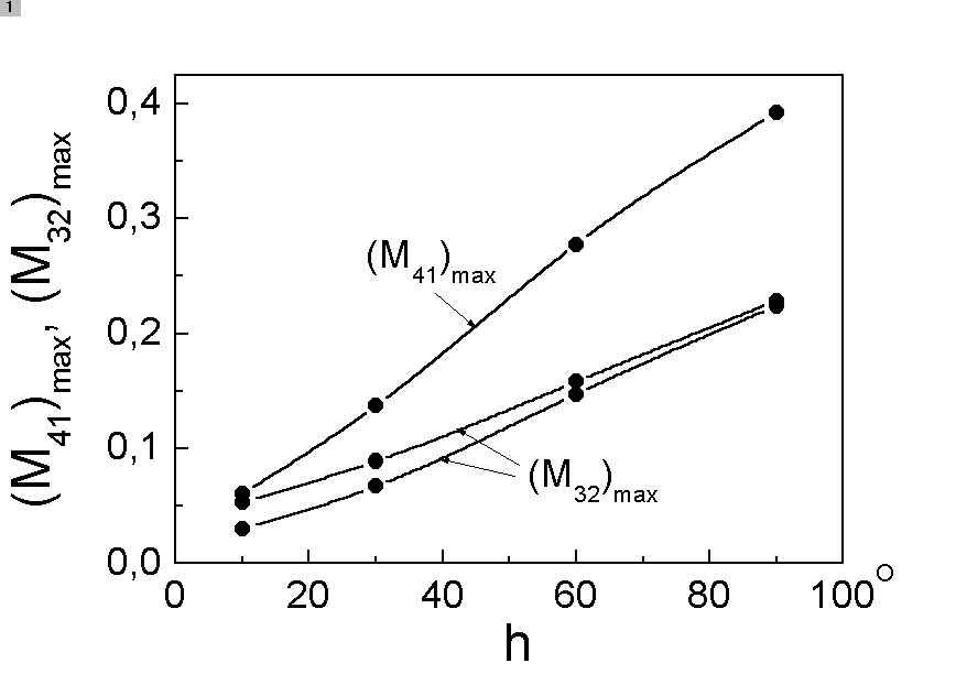
Fig.4.
Maximum values of elements
 É É  at the wavelength
  32 cm as
dependent on the elevation of the source.
The solid line refers to 32 cm as
dependent on the elevation of the source.
The solid line refers to  in the upper
half-plane, the dashed line to in the upper
half-plane, the dashed line to  in the
lower half-plane. in the
lower half-plane.
|
|
[1] Esepkina N.A., 1972, Astrophyz.Issled. (Izv.SAO), No.4, p.157.
[2] Korzhavin A.N., 1979, Astrophyz.Issled. (Izv.SAO), No.11, p.170.
|
|
|