|
|
|
|
|
For Soviet radio astronomy, the early 1960's was a period of choosing a new-generation radio telescope system and making decisions about its construction. By this time, several strong groups of radio astronomers had formed in the Soviet Union: specifically, at the Lebedev Physics Institute in Moscow, at the Institute for Radiophysics in Gor'kii, at the Armenian Academy of Sciences, and at Khar'kov in the Ukraine. By this time, the radio astronomy section of the Pulkovo Observatory had become stronger and was equipped with its own large (for those times) instrument. This section had been organized in 1953 at the initiative of S. E. Khaikin, who, after taking part in successful observations of the solar eclipse of 1947 in Brazil (when the radio emission of the solar corona was observed), became interested in radio astronomy and moved to Pulkovo from the Physics Institute. S. E. Khaikin arrived in Pulkovo with clear ideas which anticipated the development of radio astronomy many years in advance. First, he placed a stake on the centimeter wavelength range, correctly assuming that the minimum in natural noise and that the high resolution of radio telescopes would, with time, make this region essen,tial to radio astronomy. Second, he proposed (together with N. L. Kaidanovskii) a new type of radio antenna – the variable-profile antenna (VPA), which allowed this extremely necessary high angular resolution to be obtained in the centimeter region, although in only one dimension. Finally, a method (which is known as aximuth aperture synthesis) of synthesizing a two-dimensional image using a VPA was developed in Pulkovo. As long ago as 1956, the Large Pulkovo Radio Telescope (BPR), with an antenna of this type, had begun to operate in the 3-cm region with a resolution of 1 arcmin. By the early 1960's a rather large amount of operating experience had been accumulated on the BPR, and the Pulkovo group became confident that a significantly larger radio telescope could be built on this principle. The proposal to build a large radio telescope with a new, strange type of antenna was not met with enthusiasm: it provoked sharp discussions about the advantages and disadvantages of various radio telescope systems. At every meeting of ratio astronomers during that period, a discussion of the advantage of "pencil" and "knife-edge" directional patterns (with identical solid angles) flared up; the overall conclusion of these discussions was that the best was a symmetric pattern with moderate resolution or with a significantly higher resolution, at least in one dimension. This discussion was very reminiscent of the arguments between the "Little-endians" and the "Big-endians" in the land of Lilliput; there was much confusion and emotion in these discussions, but, in the end, they led to an understanding and acceptance of the concept of aperture synthesis (and, in particular, of azimuth aperture synthesis), and, in addition, of the limits imposed by "confusion noise" (see Section 3). Somewhat earlier, there were many debates about the choice of wavelength region – the meter-decimeter region, or the centimeter region, where, at that time, the sky seemed empty and receivers were not sensitive. Finally, three concrete proposals were competing against one another:
(1) a traditional, completely steerable parabloid with a reflector diameter of about 100 m,As a result of these discussions, one of the first decisions was made by the Radio Astronomy Committee of the Astronomical Council of the Academy of Sciences in 1961; they recommended that the Pulkovo Observatory develop the VPA scheme and that the other institutions develop the competing schemes. After a series of discussions, the newly organized Radio Astronomy Council of the Academy of Sciences endorsed one of the versions of a large VPA – the so-called "Academy version" (three kilometers in diameter with an element height of 20 meters – see the following subsection about the structure of a VPA). However, the final choice was made only in 1965, and it was decided to build a radio telescope according to the most developed scheme – that proposed by the groups at the Pulkovo Observatory and the Shternberg Astronomical Institute (GAISh). This radio telescope was a short-wavelength version of a VPA combined with a Kraus-type system and was named the RATAN-600. At the same time, a committee was established to choose a site, and the construction of the radio telescope was included in the Academy of Sciences plan. In 1967, the technical plan was approved and released, and, in 1968, excavation and earth moving were begun at the site which had been chosen (in the North Caucasus, near the construction site of the 6-meter optical telescope), and equipment orders were placed concurrently. In 1969, the Radio Astronomy Section of the Pulkovo Observatory was transferred to the newly organized Special Astrophysical Observatory of the Academy of Sciences of the USSR (SAO) and became the Leningrad Branch of the SAO (LF SAO). The Leningrad Branch served as the head organization, i.e., it directed all of the work associated with the planning and construction of the radio telescope and the development of instrumentation; this work was conducted side-by-side with enterprises under the Ministries of Power Engineering, Machine Engineering, Electronic Industry, and others. The most demanding, complex work was performed by the radio astronomers themselves – the staff of the Leningrad Branch of the SAO and the Radio Astronomy Section of the SAE in Zelenchukskaya. This work included the following: final surfacing of the panels (none of the enterprises drawn to the project undertook this work), putting the first sector of the main reflector into operation (the north section in 1974), the geodesic and radiometric adjustment of the main mirror and developing the corresponding instruments, and, finally, the high-sensitivity radiometers were constructed by the joint efforts of engineer-radio astronomers and enterprises in the electronics industry.(2) an earthen centimeter-wavelength bowl with a diameter of 200 m, and
(3) an array and a large variable-profile Pulkovo-type antenna.
The RATAN was officially opened in 1977, although observations began earlier (as the individual parts – the sectors – were put into operation). Development and perfection of the telescope is continuing even now.
The RATAN-600 was intended to be a general-purpose instrument, a counterweight to the tendency toward specialization, while at the same time surpassing existing telescopes in resolving power, sensitivity (both in flux density and brightness temperature), and in the accuracy with which coordinates of objects could be determined. Here, the goal of making the resolution and coordinate measurement accuracy in the radio region comparable to that in the optical region (which, at that time, was essential) was set. However, the rapid development of aperture synthesis systems and very-long-baseline interferometry has produced a revolutionary leap in resolving power and has sharply strengthened the trend toward the specialization of instruments; although the RATAN-600 has remained a general-purpose instrument to a certain extent, and is a unique instrument with respect to a combination of several parameters, it now occupies an intermediate position between the ordinary paraboloids and the powerful aperture synthesis systems with respect to individual parameters (resolution and flux density sensitivity).
In the experiment described here, an attempt was made to utilize the
unique characteristics of the RATAN. In this experiment, new observations
have been obtained, and the prospects for developing the RATAN, significantly
increasing its potential, and widening its capabilities have been explored,
taking the trends in radio astronomy which we know of into account. In
the final section, we will attempt to present the conclusions reached on
these issues from the results of Experiment Cold.
2.2. Brief Description of the RA TAN-600 Radio Telescope
2.2.1. Location of the radio telescope and its design
The RATAN-600 radio telescope (Radio Astronomy Telescope of the Academy
of
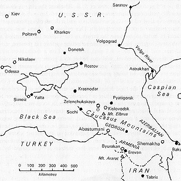
Figure 2.1 The location of the RATAN-600 radio telescope (circle with a dot) and the 6-m optical telescope (asterisk), both of which are near the village of Zelenchukskaya.
Sciences (Nauk) with a diameter of 600 meters) is located near the town of Zelenchukskaya in the North Caucasus, 20 kilometers to the northwest of the large 6-meter optical telescope (the BTA) (Fig. 2.1.). Both of these telescopes belong to the Special Astrophysical Observatory of the Academy of Sciences of the USSR and form its basic instrumental center.
The RATAN-600 is a reflector-type radio telescope, with all of the advantages following from this (a broad wavelength range, the ability to use wide bandwidths, etc.), but it is non-traditional in design. In order to obtain high resolution at rather short wavelengths, the mirror of a radio telescope must have rather large linear dimensions and the reflecting surface must be extremely accurate. These requirements are clearly contradictory; in order to resolve this contradiction, the main mirror of the telescope was built in the shape of a ring with a diameter 2R = 577 m, following the idea of S.E. Khaikin; the ring is divided into 895 individual elements with dimensions of 2m x 7.4m. Each element is a cylinder with a vertical axis and a depth of approximately 2mm (radius of curvature 1.14R). This cylindrical shape was introduced in order to decrease the errors in the surface for operation at short wavelengths, has an accurate reflecting surface (at present, s~ 0.3 mm, and it will be ~0.1 mm), is mounted on a mechanism with three degrees of freedom, and can be set to a given position in each coordinate, also with high accuracy. The mutual alignment of the elements is achieved using geodesic and radio engineering adjustment methods, and the stability of their mutual spacing is ensured by the good, stable soil, the rigid design of the elements, and the relatively low foundations (the entire structure is "one-dimensional" and flattened to the ground). Because the elements are movable, a focusing surface (in the general case, an elliptical cone), which transforms an incoming plane wave into a cylindrical wave and directs the converging beam along the ground to the secondary mirror, can be created from them. The secondary mirror collects the radiation at the focus, where the primary receiver feeds are located. The coordinates for the adjustment of each element in order to form the surface are calculated by a
computer; the computer also controls their adjustment to the specified positions.
Thus, by using a segmented mirror with controllable elements, a reflecting system with a linear size of about 600meters, capable of working down to a wavelength of 0.8 cm and even shorter, was successfully built.
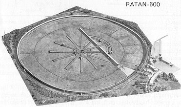
A general view of the telescope is shown in Fig. 2.2; the main mirror
and several radial and circumferential railway tracks, along which various
types of secondary mirrors (equipped with cabins containing various groups
of receivers) can be moved, are visible in Fig. 2.2. A flat, 400 m x 8
m mirror is located in the southern portion of the circle; because of this
mirror, the southern sector of the RATAN can operate as a three-mirror
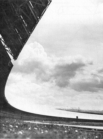
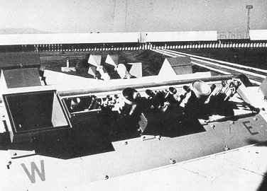
system. The north sector is shown ready for observations in Fig. 2.3.
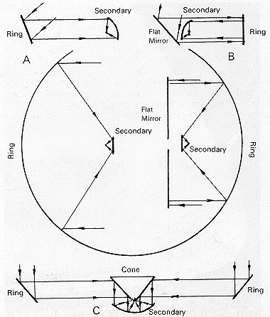
Figure 2.4 A diagram- showing the observing modes
used at the RATAN-600 radio telescope: (A) using an individual sector (two-mirror
system); (B) using the south sector, together with the plane mirror (three-mirror
system); (C) observations near the" zenith using the entire ring and a
special conical secondary mirror (Fig. 2.6).
2.2.2. Modes of operation The RATAN-600 can be used for observations in four different modes; these modes are illustrated by the diagram in Fig. 2.4.
(1) It is possible to simultaneously carry out independent
observing programs using individual sectors at various discrete azimuths
and secondary mirrors on corresponding railway tracks. At present, there
are three secondary mirrors (each of which is intended for use with one
of the sectors of the main mirror) in operation at the present time on
the RATAN. Each of these secondary mirrors is a parabolic cylinder with
a horizontal axis, 5.5 m x 8 m in size; the horizontal angle over which
the main mirror is illuminated is 100 – 110o (Fig. 25). The
position of the secondary mirror (the focus) on the railway tracks depends
on the elevation above the horizon, which can vary between 0 and 100o
and is calculated by a computer at the same time that the coordinates of
the elements included in the sector are calculated. Usually, observations
using a single sector are carried out at a fixed azimuth (i.e., the source
passes through a fixed directivity pattern, with changes from source to
source according to the source elevations (20 – 40 changes per day). In
the process, a one-dimensional image of a source is obtained in each observation.
Figure 2.5 Feed No. 1 – the secondary mirror and receiver cabins ready for operation in the sector mode.
(2) Two-dimensional images of sources can be synthesized by combining the one-dimensional images obtained from a series of successive observations of the same source at different azimuths. Azimuthal image synthesis is the second basic idea proposed by S. E. Khaikin included in the design of the RATAN.
(3) The southern sector can operate in combination with the flat periscope reflector; it then forms a Kraus-type system like those at the University of Ohio or Nanqay, France, It will be possible to track a source by moving the secondary mirror along the are-shaped railway tracks (see Fig. 2.2) after the work associated with automation is completed.
(4) Finally, using a special conical secondary mirror
installed at the center of the RATAN, it is possible to collect radiation
from the entire ring while observing near the zenith; the maximum collecting
area and
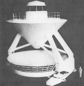

resolving power is obtained in this case. The special secondary mirror (Fig. 2.6) for this mode is presently being installed at the radio technique (Fig. 2.7).
The three operating secondary mirrors are equipped with the following specific groups of instruments:
secondary mirror No. 1: seven radiometers for the region between 1.35 and 30cm for continuum work (Fig. 2.8);At a wavelength of 8 cm, the effective collecting area in the sector mode is Seffsecondary mirror No. 2: four spectral-line receivers for studying radiation in lines at 1.35, 6.2, 18 and 21 cm;
secondary mirror No. 3: a set of ten solar radiopolarimeters for the region between 2 and 30 cm and a set of three radiometers (3.5, 2, and 8 cm) for carrying out a special program of the Shternberg Astronomical Institute (Moscow University): a complete survey of the sky at centimeter wavelengths.
More detailed information on the parameters of the radio telescope may
be found in Pariiskii et al. (1976) and Korol'kov and Pariiskii
(1979).